Reverse Engineering MenuetOS 64 - Primary Boot Loader
Background on Booting
There are two types of boot systems in x86/x64 environments: UEFI and BIOS-based. UEFI provides a standard and reference implementation for the code that executes between the CPU being released from reset and the computer transferring execution to code stored on fixed media, such as hard disks and USB drives. The code executes between these two boot stages is located on a dedicated memory chip on the motherboard, usually a form of SPI NOR storage.
But before UEFI, there were BIOS-based implementations. BIOS-based boot environments execute between the same two stage delimiters as UEFI based environments, and perform many of the same functions. However, BIOS code did not have a reference implementation or any sort of open source standard library. As such, it was up to Independent BIOS Vendors to implement the code that executes off SPI ROM and eventually transfers control over to fixed-media stored code.
A hard disk (which is a form of fixed-media storage) can contain code that should execute after the code that executes off SPI ROM. A hard disk stores data in 512-byte chunks called sectors. In BIOS-based environments, the first sector of a hard disk is the first 512 bytes stored on that hard disk. That is the very first sector of the hard disk and is known as the Master Boot Record (MBR).
When the code on the SPI NOR chip is running, the processor is in what is called 16-bit real mode. 16-bit real mode uses a 20 bit addressing scheme that divides memory into segments which are 64 kilobytes in size. The lower 16 bits are considered the offset within the segment. Segments are kept track of by the cs register. The code that runs off the SPI ROM is responsible for memory mapping the contents of the MBR to the memory address 0000:7c00.
Getting the Image
Head over to http://www.menuetos.net/download.htm and download the 64-bit version. The latest as of this writing was v1.44. Also I want to make it clear that the 64-bit version of the project is closed source. With regards to the analysis that is provided below, I have written this blog post for educational purposes and made my research freely available to all.
Analysis
Now that we have the MenuetOS 64 disk image file (M6414490.IMG), it is time to analyze! We will analyze the image file both statically and dynamically. Static analysis is reading and analyzing code without running it, whereas dynamic analysis is running the code and watching how it changes registers and memory during execution. Each analysis mode compliments the other; there are some things that can only be discerned through code execution, like register values or stack layout at a specific point in time during execution. Static analysis is useful for “filling in the blanks” when executing code to understand what the code should do next (or just did). Since MenuetOS 64 is written in Intel x64 assembly, our static analysis will consist of memory mapped disassembly in Ghidra. After reading this post, readers should understand how to launch a MenuetOS 64 virtual machine using QEMU as well as how to attach a debugger (gdb) to QEMU in order to debug while code is executing. Also, readers should understand how MenuetOS 64 begins the boot process as control of execution is passed to MenuetOS 64 code from the virtualization firmware.
MenuetOS 64 relies on legacy BIOS-based firmware for booting, as opposed to the more modern UEFI-based firmware. BIOS-based firmware relies on the Master Boot Record (MBR) disk scheme. MBR specifies a first stage executable, otherwise known as the Primary Bootloader (PBL), that exists in the first sector of the hard disk. Being constrained to one hard disk sector means the PBL can only be at a maximum 512 bytes in length. MenuetOS 64 uses only 328 of the available 512 bytes. The term “hard disk” is used in this context to refer to the virtual floppy drive that the MenuetOS image is built to run from.
MenuetOS boots off a virtual floppy disk. From a practical standpoint, this means that the floppy disk image is mapped to memory address 0x7c00. This corresponds to the first 512 bytes of the virtual floppy image file. The actual memory mapping of the floppy disk to memory address is handled by the virtualization BIOS within QEMU, and is thus beyond the scope of this writing.
As such, the very first thing we want to investigate is the first 512 bytes of M6414490.IMG. This first disk sector forms the Primary Bootloader (PBL) for the MenuetOS 64 image. This small portion of code is responsible for loading two logical units of data from disk. The first is the MenuetOS Kernel, which contains all the hand-written assembly code that powers the operating system itself. The second is the configuration for the MenuetOS installation. This configuration is a text file with specific contents that can be saved back to disk if modified. After the PBL loads both the kernel and configuration into memory, the PBL hands off control of execution to the kernel. The kernel, in turn, references the configuration data in memory.
Using either a Linux host, or Windows Subsystem for Linux (WSL), we can carve out the first 512 bytes by running the following dd command:
$ dd if=M6414490.IMG of=PBL.BIN bs=512 count=1
Figure 1: Carve out the first 512 bytes of the virtual floppy disk image using dd.
Now, we can open PBL.BIN in a hex editor. For example, using xxd:
00000000: eb3c 904d 454e 5545 544f 5300 0201 0100 .\<.MENUETOS.....
00000010: 02e0 0040 0bf0 0900 1200 0200 0000 0000 ...@............
00000020: 0000 0000 0000 2900 0000 004d 454e 5545 ......)....MENUE
00000030: 5420 3634 2020 4641 5431 3220 2020 31c0 T 64 FAT12 1.\
00000040: 8ed0 8ed8 8ec0 bc00 7cbd 317d e825 00b8 ........\|.1}.%..
00000050: 2f0e 30ff cd10 31c0 8ed0 8ed8 8ec0 bc00 /.0...1.........
00000060: 7cbd 3c7d b800 54a3 477d e807 0068 0010 \|.\<}..T.G}...h..
00000070: 6800 00cb b80e 02bb 00a0 b902 00ba 0001 h...............
00000080: e88e 0089 de56 89ef b90b 00f3 a674 0d5e .....V.......t.\^
00000090: 83c6 2081 fe00 bc72 ece9 8a00 5e8b 6c1a .. ....r....\^.l.
000000a0: b809 02bb 00a0 b902 00ba 0000 e862 00a1 .............b..
000000b0: 477d 8ec0 31db e829 0072 6b8c c783 c720 G}..1..).rk....
000000c0: 8ec7 89ef d1ef 01ef 81c7 00a0 8b05 d1ed ................
000000d0: 7303 c1e8 0425 ff0f 3df0 0f72 01c3 89c5 s....%..=..r....
000000e0: ebd4 b82e 0e30 ffcd 1089 e883 c01f b912 .....0..........
000000f0: 0031 d2f7 f152 31d2 b902 00f7 f188 c588 .1...R1.........
00000100: d658 88c1 fec1 30d2 b801 0231 dbe8 0100 .X....0....1....
00000110: c355 bd14 004d 740e 5053 5152 cd13 5a59 .U...Mt.PSQR..ZY
00000120: 5b58 72f1 5dc3 b03f b40e bb07 00cd 10eb [Xr.]..?........
00000130: fe4b 4552 4e45 4c20 204d 4e54 434f 4e46 .KERNEL MNTCONF
00000140: 4947 2020 4d4e 5400 1000 0000 0000 0000 IG MNT.........
00000150: 0000 0000 0000 0000 0000 0000 0000 0000 ................
00000160: 0000 0000 0000 0000 0000 0000 0000 0000 ................
00000170: 0000 0000 0000 0000 0000 0000 0000 0000 ................
00000180: 0000 0000 0000 0000 0000 0000 0000 0000 ................
00000190: 0000 0000 0000 0000 0000 0000 0000 0000 ................
000001a0: 0000 0000 0000 0000 0000 0000 0000 0000 ................
000001b0: 0000 0000 0000 0000 0000 0000 0000 0000 ................
000001c0: 0000 0000 0000 0000 0000 0000 0000 0000 ................
000001d0: 0000 0000 0000 0000 0000 0000 0000 0000 ................
000001e0: 0000 0000 0000 0000 0000 0000 0000 0000 ................
000001f0: 0000 0000 0000 0000 0000 0000 0000 55aa ..............U.
Figure 2: MenuetOS Primary Bootloader
We see in this hex editor output that near the beginning of the PBL.BIN file there is a string MENUETOS. This and the following 31 bytes form a FAT header that is then followed by executable code. MENUETOS seems to be a magic string denoting the “name” for the MenuetOS 64 floppy image. Magic strings are common in binary executable formats as a way of easily identifying the code that follows.
Background: BIOS Interrupt Functions
Before we begin reverse engineering the MenuetOS 64 primary bootloader, there is a small amount of prerequisite background that will help us in understanding how the PBL works. The BIOS implementation exposes several functions through semi-standardized software interrupts. The implementation of these interrupts is specific to the BIOS vendor, and in our case the BIOS is provided by the QEMU virtualization software - so we needn’t concern ourselves with the implementation except to understand the API we can utilize to send data to the BIOS to pass along to hardware devices.
The BIOS that QEMU comes bundled with for Intel processor types is called “Seabios”. If you are interested in learning more about SeaBios, head over to https://seabios.org/ or browse the project source code at https://review.coreboot.org/plugins/gitiles/seabios/+/refs/tags/rel-1.16.0.
Memory Segmentation
The segment register maps to memory at %cs multiplied by 16. For example, if the code segment register is set to the value 0x0100 and the offset is zero (0100:0000 in 16 bit real mode addressing format), this maps to memory address 0x00100000.
BIOS Interrupt I: Reading from Disk
The first interrupt we will discuss (int 0x13) allows the bootloader to read arbitrary data from disk into memory. The reason why this is necessary is because the PBL needs to load a more fully featured Secondary Bootloader (SBL) and then transfer control of execution to it. One of the arguments to int 0x13 is the memory location to load the contents of the disk to. Since the PBL executes in real mode, it uses a segmented memory model. The %es register contains the segment and %bx contains the offset within the segment to write the data at. Another important argument is the value stored in %al, which determines the number of sectors to be read from disk. Lastly, it is important to note that the carry flag is set on the %eflags register upon failure. This means if the carry flag is not set, the operation was successful.
The SBL is responsible for transitioning from 16-bit real mode to 64-bit extended mode as well as for loading the kernel into memory. Once the kernel is loaded into memory, the SBL transfers control of execution to the kernel, whereby the OS has fully booted.
There is a great description of the BIOS interrupt handlers in the legacy grub implementation for the primary bootloader. These comments are located in the grub legacy project at stage1/stage1.S. This makes sense, as the legacy grub implementation is also a primary bootloader for BIOS-based systems, performing many of the same functions as the MenuetOS 64 PBL.
/*
* BIOS call "INT 0x13 Function 0x2" to read sectors from disk into memory
* Call with
* %ah = 0x2
* %al = number of sectors
* %ch = cylinder
* %cl = sector (bits 6-7 are high bits of "cylinder")
* %dh = head
* %dl = drive (0x80 for hard disk, 0x0 for floppy disk)
* %es:%bx = segment:offset of buffer
* Return:
* %al = 0x0 on success; err code on failure
*/
Figure 3: BIOS Interrupt documentation for disk read from grub-legacy source code
Source: https://salsa.debian.org/grub-team/grub-legacy/-/blob/debian/0.97-80/stage1/stage1.S#L325
BIOS Interrupt II: Printing to Video Out
The second interrupt we need to be aware of (int 0x10) writes a given ASCII character to the terminal character device. By passing a character as the lower byte of %ax and issuing the int 0x10 instruction, that character will be printed out on the video output screen.
/*
* Use BIOS "int 10H Function 0Eh" to write character in teletype mode
* %ah = 0xe %al = character
* %bh = page %bl = foreground color (graphics modes)
*/
Figure 4: BIOS Interrupt documentation for print character from grub-legacy source code
Source: https://salsa.debian.org/grub-team/grub-legacy/-/blob/debian/0.97-80/stage1/stage1.S#L415
If you are interested in learning more about other BIOS-based interrupts, there is a comprehensive x86 BIOS Interrupt List on the web: http://www.cs.cmu.edu/~ralf/files.html.
Static Analysis
To perform static analysis of this section of code, we need to analyze it in 16-bit Intel x86 Real Mode. In Ghidra, we import PBL.BIN as a Raw binary using the LanguageID x86:LE:16:Real:Mode:default.
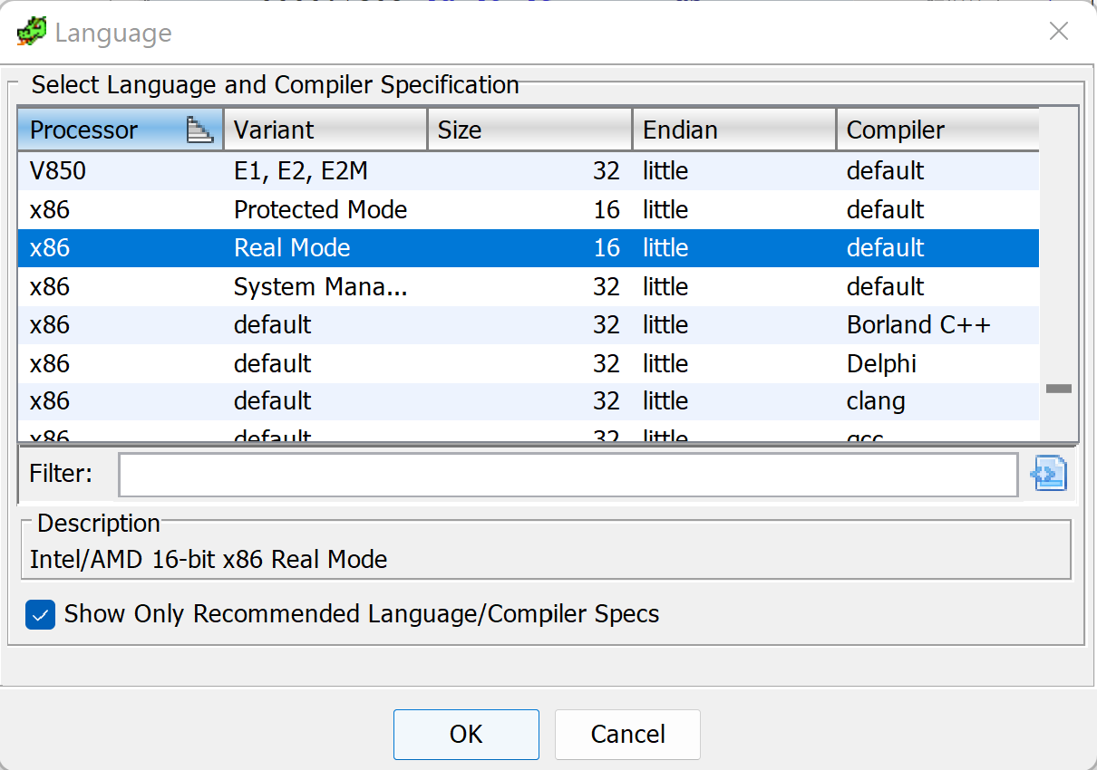
Figure 5: Selecting the appropriate LanguageID within Ghidra’s Import Binary workflow.
After selecting the LanguageID, we need to set the base address. As noted before, this is the default MBR load address, which is 0x7c00.
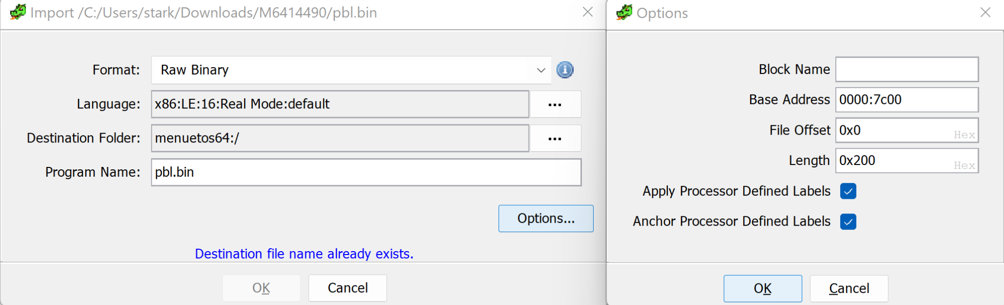
Figure 6: Setting the proper Base Address within Ghidra’s Import Binary workflow.
After importing the binary and opening it in Ghidra’s CodeBrowser, we will see the disassembly of the MBR record. Please note that in the following disassembly, I created all annotations to make it clear what action each function or label is performing.
//
// ram
// ram:0000:7c00-ram:0000:7dff
//

assume DF = 0x0 (Default)
0000:7c00 eb 3c JMP _start
0000:7c02 90 NOP
0000:7c03 4d 45 4e ds "MENUETOS"
          55 45 54
          4f 53 00
[...]
0000:7c2b 4d 45 4e ds "MENUET 64 FAT12 "
          55 45 54
          20 36 34
          _start
0000:7c3e 31 c0 XOR AX,AX
0000:7c40 8e d0 MOV SS,AX
0000:7c42 8e d8 MOV DS,AX
0000:7c44 8e c0 MOV ES,AX
0000:7c46 bc 00 7c MOV SP,0x7c00
0000:7c49 bd 31 7d MOV BP,0x7d31
0000:7c4c e8 25 00 CALL _load_next_stage
0000:7c4f b8 2f 0e MOV AX,0xe2f
0000:7c52 30 ff XOR BH,BH
0000:7c54 cd 10 INT 0x10
0000:7c56 31 c0 XOR AX,AX
0000:7c58 8e d0 MOV SS,AX
0000:7c5a 8e d8 MOV DS,AX
0000:7c5c 8e c0 MOV ES,AX
0000:7c5e bc 00 7c MOV SP,0x7c00
0000:7c61 bd 3c 7d MOV BP,0x7d3c
0000:7c64 b8 00 54 MOV AX,0x5400
0000:7c67 a3 47 7d MOV [0x7d47],AX
0000:7c6a e8 07 00 CALL _load_next_stage
0000:7c6d 68 00 10 PUSH 0x1000
0000:7c70 68 00 00 PUSH 0x0
0000:7c73 cb RETF

*************************************************************
* FUNCTION
*************************************************************

          undefined __cdecl16near _load_next_stage ()
0000:7c74 b8 0e 02 MOV AX,0x20e
0000:7c77 bb 00 a0 MOV BX,0xa000
0000:7c7a b9 02 00 MOV CX,0x2
0000:7c7d ba 00 01 MOV DX,0x100
0000:7c80 e8 8e 00 CALL _read_disk_sectors
0000:7c83 89 de MOV SI,BX
          LAB_0000_7c85
0000:7c85 56 PUSH SI
0000:7c86 89 ef MOV DI,BP
0000:7c88 b9 0b 00 MOV CX,0xb
0000:7c8b f3 a6 CMPSB.RE ES:DI,SI
0000:7c8d 74 0d JZ LAB_0000_7c9c
0000:7c8f 5e POP SI
0000:7c90 83 c6 20 ADD SI,0x20
0000:7c93 81 fe 00 bc CMP SI,0xbc00
0000:7c97 72 ec JC LAB_0000_7c85
0000:7c99 e9 8a 00 JMP _print_question_mark
          LAB_0000_7c9c
0000:7c9c 5e POP SI
0000:7c9d 8b 6c 1a MOV BP,word ptr [SI + 0x1a]
0000:7ca0 b8 09 02 MOV AX,0x209
0000:7ca3 bb 00 a0 MOV BX,0xa000
0000:7ca6 b9 02 00 MOV CX,0x2
0000:7ca9 ba 00 00 MOV DX,0x0
0000:7cac e8 62 00 CALL _read_disk_sectors
0000:7caf a1 47 7d MOV AX,[0x7d47]
0000:7cb2 8e c0 MOV ES,AX
0000:7cb4 31 db XOR BX,BX
          LAB_0000_7cb6
0000:7cb6 e8 29 00 CALL _print_period
0000:7cb9 72 6b JC _print_question_mark
0000:7cbb 8c c7 MOV DI,ES
0000:7cbd 83 c7 20 ADD DI,0x20
0000:7cc0 8e c7 MOV ES,DI
0000:7cc2 89 ef MOV DI,BP
0000:7cc4 d1 ef SHR DI,0x1
0000:7cc6 01 ef ADD DI,BP
0000:7cc8 81 c7 00 a0 ADD DI,0xa000
0000:7ccc 8b 05 MOV AX,word ptr [DI]
0000:7cce d1 ed SHR BP,0x1
0000:7cd0 73 03 JNC LAB_0000_7cd5
0000:7cd2 c1 e8 04 SHR AX,0x4
          LAB_0000_7cd5
0000:7cd5 25 ff 0f AND AX,0xfff
0000:7cd8 3d f0 0f CMP AX,0xff0
0000:7cdb 72 01 JC LAB_0000_7cde
0000:7cdd c3 RET
          LAB_0000_7cde
0000:7cde 89 c5 MOV BP,AX
0000:7ce0 eb d4 JMP LAB_0000_7cb6

*************************************************************
* FUNCTION
*************************************************************
          undefined __cdecl16near _print_period ()
0000:7ce2 b8 2e 0e MOV AX,0xe2e
0000:7ce5 30 ff XOR BH,BH
0000:7ce7 cd 10 INT 0x10
0000:7ce9 89 e8 MOV AX,BP
0000:7ceb 83 c0 1f ADD AX,0x1f
0000:7cee b9 12 00 MOV CX,0x12
0000:7cf1 31 d2 XOR DX,DX
0000:7cf3 f7 f1 DIV CX
0000:7cf5 52 PUSH DX
0000:7cf6 31 d2 XOR DX,DX
0000:7cf8 b9 02 00 MOV CX,0x2
0000:7cfb f7 f1 DIV CX
0000:7cfd 88 c5 MOV CH,AL
0000:7cff 88 d6 MOV DH,DL
0000:7d01 58 POP AX
0000:7d02 88 c1 MOV CL,AL
0000:7d04 fe c1 INC CL
0000:7d06 30 d2 XOR DL,DL
0000:7d08 b8 01 02 MOV AX,0x201
0000:7d0b 31 db XOR BX,BX
0000:7d0d e8 01 00 CALL _read_disk_sectors
0000:7d10 c3 RET

*************************************************************
* FUNCTION
*************************************************************

          undefined __cdecl16near _read_disk_sectors ()
0000:7d11 55 PUSH BP
0000:7d12 bd 14 00 MOV BP,0x14
          _read_sectors_loop
0000:7d15 4d DEC BP
0000:7d16 74 0e JZ _print_question_mark
0000:7d18 50 PUSH AX
0000:7d19 53 PUSH BX
0000:7d1a 51 PUSH CX
0000:7d1b 52 PUSH DX
0000:7d1c cd 13 INT 0x13
0000:7d1e 5a POP DX
0000:7d1f 59 POP CX
0000:7d20 5b POP BX
0000:7d21 58 POP AX
0000:7d22 72 f1 JC _read_sectors_loop
0000:7d24 5d POP BP
0000:7d25 c3 RET
          _print_question_mark
0000:7d26 b0 3f MOV AL,0x3f
0000:7d28 b4 0e MOV AH,0xe
0000:7d2a bb 07 00 MOV BX,0x7
0000:7d2d cd 10 INT 0x10
          _tight_loop
0000:7d2f eb fe JMP _tight_loop
0000:7d31 4b 45 52 ds "KERNEL MNTCONFIG MNT"
          4e 45 4c
          20 20 4d
[...]
Figure 7: Ghidra disassembly of Primary Boot Loader
Overall the flow of the first stage bootloader is to load the next boot stage from disk into memory at address 0x10000 and then transfer execution to the instructions that exist at that memory address. The PBL does this by using BIOS interrupts to read all sectors from the virtual floppy disk into memory at a specific address. Data is stored on the virtual floppy disk in Cylinder-Head-Sector format. This is an older format that breaks data on disk into addressable chunks or blocks. The implementation doesn’t use the Cylinder or Head parameters of this addressing scheme, making sectors the most important component of data addressing.
Instruction by Instruction
0000:7c00 eb 3c JMP _start
Figure 8: First executable instruction
This is the very first instruction that MenuetOS 64 executes. It transfers control of execution to the location 0x3c bytes beyond the current value of the %pc register, which I have labeled _start.
_start
0000:7c3e 31 c0 XOR AX,AX
0000:7c40 8e d0 MOV SS,AX
0000:7c42 8e d8 MOV DS,AX
0000:7c44 8e c0 MOV ES,AX
0000:7c46 bc 00 7c MOV SP,0x7c00
0000:7c49 bd 31 7d MOV BP,0x7d31
0000:7c4c e8 25 00 CALL _load_next_stage
Figure 9: _start label
This can be thought of as the main function for the primary bootloader operations. This code loads different chunks of data from disk into memory and then performs a far return to the memory location where the disk contents are loaded.
The first four lines clear the segment registers, and then lines 5-6 set the stack pointer (%sp) and the base pointer (%bp), effectively setting up the stack. There are two calls to _load_next_stage in the _start function. Between the two calls is a BIOS Interrupt to print a forward slash to the video output.
0000:7c4f b8 2f 0e MOV AX,0xe2f
0000:7c52 30 ff XOR BH,BH
0000:7c54 cd 10 INT 0x10
Figure 10: BIOS Interrupt for Video Out
After the three instructions to print the forward slash, there is the second call to _load_next_stage. Like before the first call, the segment registers are zeroed out and the stack pointer is assigned to the same value as before. However, the base pointer is a slightly higher memory address, denoting a larger stack. The last two instructions before the CALL instruction move the immediate value 0x5400 to the memory location 0x7d7.
0000:7c56 31 c0 XOR AX,AX
0000:7c58 8e d0 MOV SS,AX
0000:7c5a 8e d8 MOV DS,AX
0000:7c5c 8e c0 MOV ES,AX
0000:7c5e bc 00 7c MOV SP,0x7c00
0000:7c61 bd 3c 7d MOV BP,0x7d3c
0000:7c64 b8 00 54 MOV AX,0x5400
0000:7c67 a3 47 7d MOV [0x7d47],AX
0000:7c6a e8 07 00 CALL _load_next_stage
Figure 11: Caller for _load_next_stage
The last three instructions of this routine push two values onto the stack. These values are specific to the far return instruction which is the third instruction. The far return instruction pops two 16-bit values off the stack and uses them to return to a location. The first value is popped into %ip and the second value is popped into %cs.
0000:7c6d 68 00 10 PUSH 0x1000
0000:7c70 68 00 00 PUSH 0x0
0000:7c73 cb RETF
Figure 12: Far return to transfer control of execution to loaded disk sectors
_load_next_stage
After the stack pointers are initialized, the primary code stub (_start) calls a function which I have called _load_next_stage. %ax, %bx, %cx, and %dx are all arguments to the _read_disk_sectors function. _load_next_stage begins by setting these arguments for a call to the function _read_disk_sectors.
0000:7c74 b8 0e 02 MOV AX,0x20e
0000:7c77 bb 00 a0 MOV BX,0xa000
0000:7c7a b9 02 00 MOV CX,0x2
0000:7c7d ba 00 01 MOV DX,0x100
0000:7c80 e8 8e 00 CALL _read_disk_sector
Figure 13: _read_disk_sector caller within _load_next_stage
Referring to the comments we identified within the legacy grub code, we can understand what each one of these bytes means:
| Register | Value (Hex) | Value (Decimal) | Meaning | |
|---|---|---|---|---|
| %ah | 0x2 | 2 | INT 13 Function Id | |
| %al | 0xe | 14 | Number of Sectors to Read | |
| %bx | 0xa000 | 40960 | Memory segment offset for writing data from disk sectors to | |
| %ch | 0x0 | 0 | Cylinder to read from | |
| %cl | 0x2 | 2 | Sector to read from | |
| %dh | 0x1 | 1 | Head to read from | |
| %dl | 0x0 | 0 | Drive (0x0 for floppy, 0x80 for hard disk) |
Stated otherwise, this piece of code will read 14 floppy disk sectors starting at sector 2 (offset 0:0x0400) and load the data from that location into the memory region beginning with address 0xa000.
The next section of code attempts to read data off of the virtual floppy disk at a specific sector, incrementing the sector index after every successful read. If the read fails, the program skips to _print_question_mark. _print_question_mark is a sort of error handling routine, whereby if some disk read operation fails, the question mark character is printed out to the console and then the entire system goes into a tight loop that it cannot break out of.
0000:7c83 89 de MOV SI,BX
          LAB_0000_7c85
0000:7c85 56 PUSH SI
0000:7c86 89 ef MOV DI,BP
0000:7c88 b9 0b 00 MOV CX,0xb
0000:7c8b f3 a6 CMPSB.RE ES:DI,SI
0000:7c8d 74 0d JZ LAB_0000_7c9c
0000:7c8f 5e POP SI
0000:7c90 83 c6 20 ADD SI,0x20
0000:7c93 81 fe 00 bc CMP SI,0xbc00
0000:7c97 72 ec JC LAB_0000_7c85
0000:7c99 e9 8a 00 JMP _print_question_mark
Figure 14: caller for _print_question_mark
_read_disk_sectors
This function is responsible for actually performing the interrupt instruction for reading data from the disk. It utilizes %ax, %bc, %cx, %dx as arguments specified by the caller. The function loops until the disk read fails. Remember, when the read fails, the carry bit is set. The function should load no more than 20 (0x14) sectors as BP is set to this value and decremented by one on every iteration. If BP reaches zero, the subroutine breaks out by JMP’ing to _print_question_mark, which is a general error condition denoting something unexpected happened. What sort of unexpected operation might happen? The disk image might be truncated improperly, leading to load a full sector that might not entirely exist.
          undefined __cdecl16near _read_disk_sectors ()
0000:7d11 55 PUSH BP
0000:7d12 bd 14 00 MOV BP,0x14
          _read_sectors_loop
0000:7d15 4d DEC BP
0000:7d16 74 0e JZ _print_question_mark
0000:7d18 50 PUSH AX
0000:7d19 53 PUSH BX
0000:7d1a 51 PUSH CX
0000:7d1b 52 PUSH DX
0000:7d1c cd 13 INT 0x13
0000:7d1e 5a POP DX
0000:7d1f 59 POP CX
0000:7d20 5b POP BX
0000:7d21 58 POP AX
0000:7d22 72 f1 JC _read_sectors_loop
0000:7d24 5d POP BP
0000:7d25 c3 RET
Figure 15: _read_sectors_loop caller
Experiment
What happens if we truncate half the virtual floppy image and try to boot it? Cut the floppy disk in half and find out! The version of MenuetOS 64 we are testing against is 1474560 bytes in length. Divided by two, the size is 737280. We run the following Linux command to take the first half of the virtual floppy disk image:
$ dd if=M6414490.IMG of=M6414490.HALF.IMG bs=737280 count=1
Now let’s see what happens when we try to run the first half of the image:
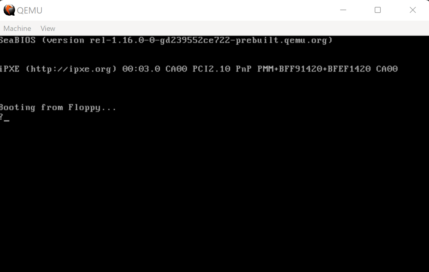 Figure 16: QEMU Video output of error state
Likewise, if we have a debugger attach at this point and we send an interrupt signal by pressing CTRL+C at the gdb prompt, we will see that the CPU is in the tight loop that is the last instruction of the PBL:
Program received signal SIGINT, Interrupt.
0x0000000000007d2f in ?? ()
(gdb) x/1i $rip
=> 0x7d2f: jmp 0x7d2f
Figure 17: Code breakpoint for error condition.
_print_question_mark
As noted above, this subroutine exists as an error handler for the rest of the PBL. This group of five instructions simply prints out a question mark character to the console, and then continues executing to a JMP instruction that JMP’s to itself, forming a tight loop that the processor is not able to break out of. This is most likely for debugging purposes - to allow the developer to understand what sector the disk read failed at. In any other operating system, it would probably make more sense to HLT the CPU at this point; or to at least RESET.
      _print_question_mark
0000:7d26 b0 3f MOV AL,0x3f
0000:7d28 b4 0e MOV AH,0xe
0000:7d2a bb 07 00 MOV BX,0x7
0000:7d2d cd 10 INT 0x10
        _tight_loop
0000:7d2f eb fe JMP _tight_loop
Figure 18: error condition static analysis disassembly.
Dynamic Analysis
What happens when we run the Linux file command against our virtual floppy disk image?
$ file M6414490.IMG
M6414490.IMG: DOS/MBR boot sector, code offset 0x3c+2, OEM-ID
"MENUETOS", root entries 224, sectors 2880 (volumes \<=32 MB),
sectors/FAT 9, sectors/track 18, serial number 0, label: "MENUET 64 ",
FAT (12 bit), followed by FAT
Figure 19: file command output for MenuetOS 64 virtual floppy image.
How do we run our virtual image?
qemu-system-x86_64.exe -drive
"file=M6414490.IMG,format=raw,if=floppy" -boot a -m 1024 -gdb
tcp::1234 -S
Argument descriptions:
- -drive: specifies a drive that MenuetOS 64 will boot from.
- file: this is the path to the MenuetOS 64 floppy image
- if: mark the drive as a floppy drive
- format: needs to be raw so that disk writes to block 0 can occur. Skipping this argument results in an errors like this:
WARNING: Image format was not specified for 'M6414490.IMG' and probing guessed raw.

Automatically detecting the format is dangerous for raw images, write operations on block 0 will be restricted.

Specify the 'raw' format explicitly to remove the restrictions.
- -boot: sets the boot device to the floppy drive (a)
- -m: specifies 1G of RAM
- -gdb: expose GDB stub on TCP port 1234.
- -S: do not start the CPU until a client connects to the GDB stub.
We need to connect to the QEMU gdb stub (target remote :1234). Next we need to set a breakpoint at the memory location 0x7c00 (b *0x7c00). After the breakpoint is set, we can then continue execution (c).
$ gdb

[...]
(gdb) target remote :1234
Remote debugging using :1234
[...]
0x000000000000fff0 in ?? ()
(gdb) b *0x7c00
Breakpoint 1 at 0x7c00
(gdb) c
Continuing.
Breakpoint 1, 0x0000000000007c00 in ?? ()
(gdb) display/16i $pc
1: x/16i $pc
=> 0x7c00: jmp 0x7c3e
0x7c02: nop
[...]
(gdb) stepi
0x0000000000007c3e in ?? ()
1: x/16i $pc
=> 0x7c3e: xor %eax,%eax
0x7c40: mov %eax,%ss
0x7c42: mov %eax,%ds
0x7c44: mov %eax,%es
0x7c46: mov $0x31bd7c00,%esp
0x7c4b: jge 0x7c35
0x7c4d: and $0xe2fb800,%eax
0x7c52: xor %bh,%bh
0x7c54: int $0x10
0x7c56: xor %eax,%eax
0x7c58: mov %eax,%ss
0x7c5a: mov %eax,%ds
0x7c5c: mov %eax,%es
0x7c5e: mov $0x3cbd7c00,%esp
0x7c63: jge 0x7c1d
0x7c65: add %dl,0x47(%rbx,%riz,4)
(gdb) info reg
rax 0xaa55 43605
rbx 0x0 0
rcx 0x0 0
rdx 0x0 0
rsi 0x0 0
rdi 0x0 0
rbp 0x0 0x0
rsp 0x6f00 0x6f00
r8 0x0 0
r9 0x0 0
r10 0x0 0
r11 0x0 0
r12 0x0 0
r13 0x0 0
r14 0x0 0
r15 0x0 0
rip 0x7c3e 0x7c3e
eflags 0x202 [ IOPL=0 IF ]
[...]
Figure 21: Example GDB session attached to MenuetOS 64 PBL.
When gdb breaks at 0x7c00, we can analyze the state of the VM before it has executed any instructions contained in M6414490.IMG. We can then step through each instruction (stepi) and examine how the registers and stack change. At this point, the video output looks like this:
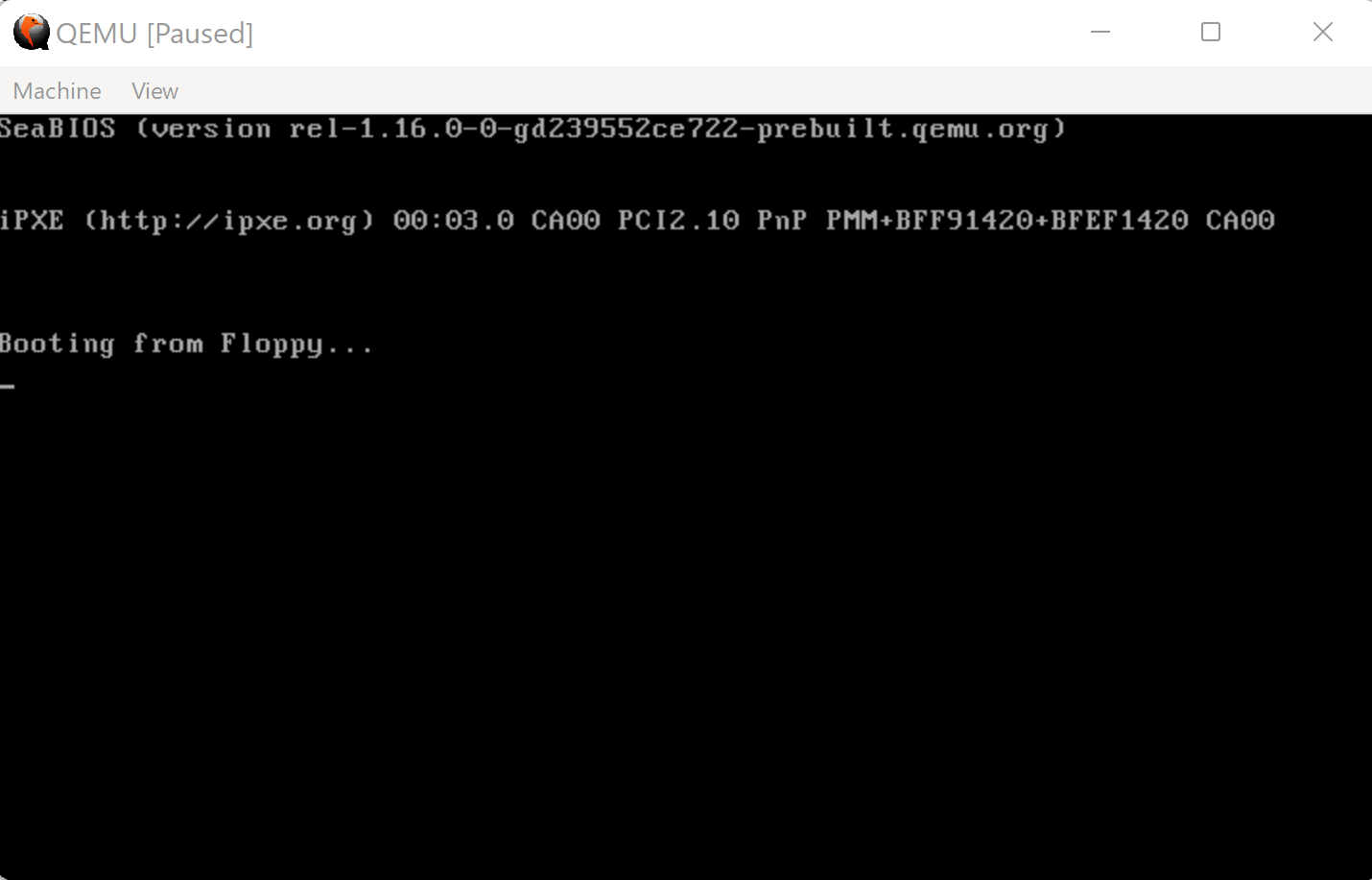
Figure 22: QEMU Video output before any MenuetOS 64-specific instructions have been executed.
Let’s try setting a breakpoint after this line of code executes, at memory address 0x7c56:
0000:7c54 cd 10 INT 0x10
If we let execution continue to this break point, the video output changes to look like this:
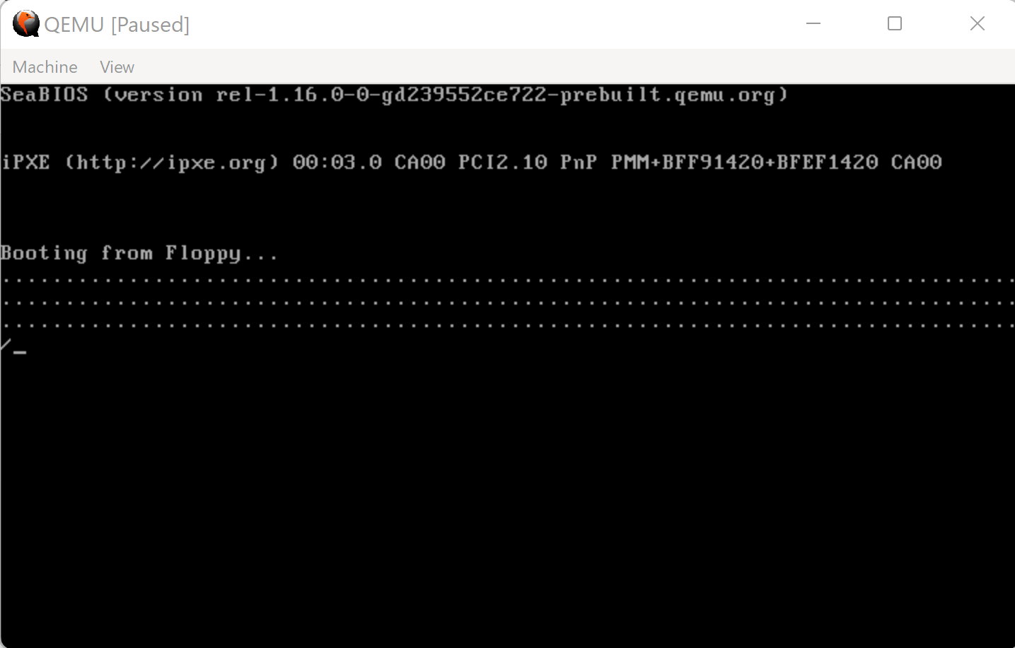
Figure 23: QEMU Video Output after the rest of the MenuetOS 64 image is loaded from floppy into memory.
The video output displays a long string of periods (ASCII: 0x2e); one for each disk sector loaded from the virtual floppy disk. The period string is concluded by a forward slash (ASCII: 0x2f). This forward slash signifies that the kernel has been loaded and that all periods that will follow signify the configuration data being loaded from disk into memory.
What happens at the end of the PBL under normal operating systems, when all disk sectors have been read into memory as expected? We know that the far return is going to jump to physical memory address 0x10000, so let us see what kind of data exists at this memory address at this point.
(gdb) x/i 0x10000
0x10000: jmp 0x10776
Unfortunately, setting a breakpoint at 0x10000 results in a GDB error:
Program received signal SIGTRAP, Trace/breakpoint trap.
But we do know now that immediately upon execution of this instruction the kernel will JMP to memory address 0x10776, and setting a breakpoint there will pause execution as expected.
We also find that the location of this code is at offset 0xf400 in the M6414490.IMG file.
Conclusion
This has been a brief look at the primary bootloader for MenuetOS 64-bit.